Why Pooling Exists
If a single node serves all UEs in a given area, its capacity has to be dimensioned for that area's own peak load, even though average demand is typically much lower than combined demand of that region comprising of those areas. peak . Since the timing of peak load often varies across different areas — one area may peak during the morning commute, another during an evening event — pooling capacity across several areas allows the combined pool to be dimensioned closer to combined peak demand of that region rather than the sum of each area's individual peak, making more efficient use of overall network capacity.
Pooling also brings benefits beyond capacity efficiency. It provides redundancy: if one node in the pool fails, the UEs it was serving can be picked up by another node in the same pool, rather than losing service entirely. It enables load balancing: demand can be distributed across the pool's nodes rather than concentrated wherever a UE happens to be located. And it reduces signalling overhead: a UE moving between cells served by different nodes within the same pool area can often remain anchored to the same node throughout, avoiding the relocation signalling that would otherwise be needed each time it crosses into new coverage.
MME Pooling
Fig-1 depicts 4 MMEs in a pool serving 7 eNodeBs. Identifiers associated with the MMEs are utilised to manage pooling mechanism. MME group identifier (MMEG) refers to the name of pool, MME belongs to while MMEC identifies Each of the MME in the pool. MMEI is formed by the combination of MMEGI and MMEC. When a terminal which is already registered, sends a request to MME, this request first reaches eNodeB and it contains GUTI within which MMEI is encapsulated. eNodeB checks MMEI in GUTI code, whether the MMEG is within the pool of MMEs with which it is connected. Then, it forwards the message to the intended MME.
However, If the GUTI is absent or it points to an MME that is not within the pool associated with that eNodeB, the eNodeB selects a new MME and forwards the service request to the selected MME. The MME then returns a GUTI to the eNodeB, which includes its own MMEI.
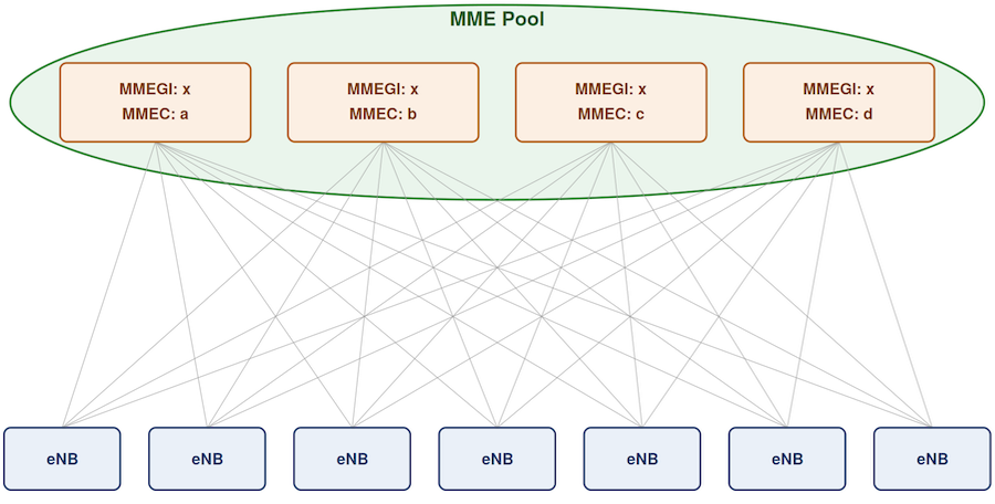
Figure 1: MME Pooling
Rather than selecting MME, which may result in overload in some of them, eNodeB selects MME based on weight factor of each of the MME in the pool. While configuring, MME is assigned a weight factor based on it’s capacity, the MME informs this weight factor to all the eNodeBs with which it is connected. The eNodeBs can distribute UEs across the pool of MMEs accordingly.
There are certain situations where it may be useful to manipulate the weighting factor of an MME. For example if there is a set of eNodeBs and associated pool of MMEs and a new MME is to inserted in the MME pool. The New MME can inform the eNodeBs that is has a higher weight factor than the actual value it will have during “normal” operations. This means that the new MME will be allocated UEs on a higher priority some by eNodeBs. Once the new MME reaches a comparable load to existing MMEs, it will reduce its weight factor to normal and inform the eNodeBs of this change.
The implementation of pooling optimises MME capacity planning. Wi in the core network architecture also implies some changes with regard to network dimensioning. In the hierarchical systems, when you dimension your system, you will generally apply some general formula, for example peak load plus an additional 20% capacity, in order to handle extra load. This is dimensioned across an area, however, not one particular region as with a pooled network architecture. This means that the numbers of subscribers that you are dealing with when calculating excess capacity are significantly different.
Sometimes, For performing maintenance activities on a MME, UEs already registered with a MME have to be moved to other MMEs in the same pool, by triggering O&M operations. By changing weight factor of this MME ahead of time, eNodeBs can divert new UEs to other MMEs, so that number of UEs which have to be moved to other MMEs can be reduced.
Moving a UE from One MME to Another (Load Rebalancing)
When an operator needs to redistribute load away from one MME onto others in the pool, how this is done depends on whether the target UE is currently connected or idle.
For a UE in connected mode, the network can act directly: it uses an S1 release procedure, carrying a specific cause value — "load balancing TAU required" — that tells the UE to release its connection with the current MME and immediately perform a Tracking Area Update, without reusing any of the old MME's identifying parameters (such as its GUMMEI). Because the UE deliberately omits the old MME's identifiers during this TAU, the network is free to assign it to a different MME in the pool rather than reconnecting it to the same one. A similar effect can also be achieved through other mechanisms, such as deliberately allowing an S1 connection to become inactive, which likewise causes the UE to be released.
For a UE in idle mode, the situation is different: there's no active S1 connection to release in the first place, so the network has two options:
- Wait passively — take no immediate action, and simply apply the reassignment the next time the UE naturally contacts the network on its own (for example, through an ordinary attach or periodic Tracking Area Update).
- Page the UE proactively — deliberately bring the idle UE into connected mode by paging it first, and then trigger the same S1 release procedure used for already-connected UEs, forcing the reassignment immediately rather than waiting for the UE's next natural contact.
Regardless of which mechanism is used, this rebalancing must be done gradually — moving UEs into other MMEs in the pool a few at a time, rather than redirecting a large number of UEs onto the same target MME(s) simultaneously, which can cause overload problem.